
Computer-Mounted Smartphone Stand
This project was completed during my junior year for the ‘Automation and Manufacturing Methods’ course at Boston University. The aim of the project was to create a product that could be manufactured in the Boston University Automated Design and Manufacturing Laboratory (ADML) using only two parts. This had to be done by implementing a variety of manufacturing strategies, including computer-integrated manufacturing (CIM) control, scheduling through routing diagrams and work-in-progress, throughput, and cycle analysis, and implementation of lean principles.
Our two-person group decided to make a computer-mounted smartphone stand that would allow for users to use their phone alongside their computer. We decided on this product as having a conveniently-placed device that could be used as a second monitor would be quite useful in work-from-home situations, and current alternatives seemed to be lacking in certain ways such as durability.
This project was really useful in my development as an engineer as it allowed me to design a product to be manufactured in a fully automated manner. It forced me to think of my product in terms of manufacturability rather than just thinking about its purpose, which definitely affected the way our team designed our parts - we sought to decrease the processing time as much as possible, thus simplifying our geometry and using stock pieces that were quite close to the final product. We made multiple prototypes and redesigned our parts multiple times in order to make them more easily manufactured and assembled in an automated setting, adding components such as chamfers in order to reduce the possibility of error by the robotic arms used. In addition to this, the technical aspects such as scheduling, lean principles, and process analysis really gave me a lot of tools to further assess automated manufacturing processes in terms of their bottleneck, efficiency, and statistical control.
Collaborators
Skills
CAD (SolidWorks)
Gibbs
CAM
CIM
Process Scheduling
DFM


Design Process
The product consists of two parts: a base that latches onto the computer and a backboard that supports the smartphone. The base has ridges with 0.6in of separation between them in order to accommodate the smartphone and a case comfortably and allowing for the phone to be placed at a variety of angles. The base was machined from 3in x 1.5in x 1.25in HDPE stock, and the backboard was made from 3in x 2in x 0.25in HDPE stock. The outer dimensions were kept the same in the finalised pieces to reduce machining time.
Chamfers were used to allow for easy assembly by the robotic arms, and rounds were designed into the parts to account for the size of the mill bits used. The base required two separate milling processes in order to create the desired geometry.
First milling process done on base part
Second milling process done on base part after repositioning
Single process done on rest part
Manufacturing Strategy
Based on the process charts of a previously-made product, our team was able to create computer integrated manufacturing (CIM) charts to estimate processing times and create a routing diagram.
Based on these, we developed a work-in-process (WIP) table to analyse our throughput, cycle time, and bottleneck. We found that the throughput, at steady state, was 18.756 parts/hour.
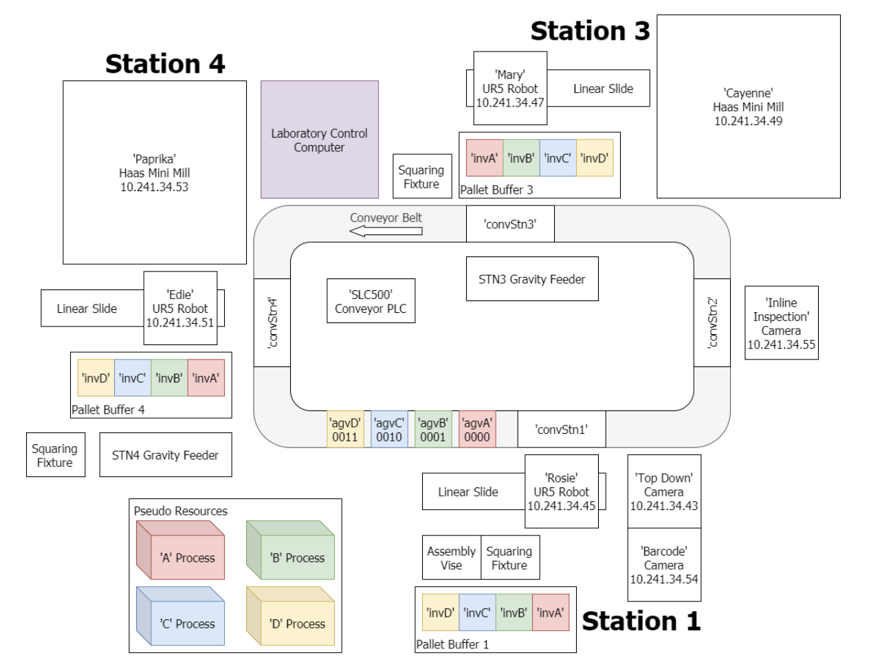
Diagram of the Boston University ADML Flexible Manufacturing Cell
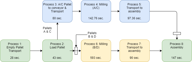
Routing diagram for our process, with the bottleneck being process 6
(milling of base part)