
Drinking Water Rotary Vane Pump
This project was completed for the ‘Manufacturing Processes for Design and Production’ course at Boston University. The goal of the project was to design a rotary vane pump to be used with drinking water containing fluoride and chlorine, in an outdoor setting with a MTBF of 2 years at a 50% duty cycle. I was in charge of material selection for the different components coming in contact with the drinking water, as well as the dimensioning of slots and clearance holes for the different fasteners including dowel pins and socket head cap screws, accounting for wrench clearance as well. I also was in charge of modelling the parts, creating an assembly, and producing some of the engineering drawings in OnShape.
In addition, the project also required the manufacturing of a rotary vane pump from a provided set of drawings using Boston University's Engineering Product Innovation Center (EPIC) facilities.
This project was a great exercise in how to select and analyse different components (material, fasteners, bearings) for a specific task, ensuring that these are compatible with the intended purpose and can last for the necessary amount of time prior to needing maintenance. In addition, the physical manufacturing part of the project was also helped me learn how different manufacturing processes can be applied to develop a part, as well as their limitations.
Collaborators
Skills
Material Selection (Ansys Granta)
CAD (OnShape)
Prototyping
GD&T and Engineering Drawings
Manual Milling and Turning
Sheet Metal Bending
Waterjet Cutting

Design Process for Drinking Water Pump
The documents below show the engineering drawings for the drinking water pump designed, as well as the justification for the design choices made.
Manufacturing and Assembly of Rotary Vane Pump
Part of the project was to manufacture and assemble a rotary vane pump from a provided set of drawings. This included using a milling the vanes, press-fitting the bearings into their respective housings, turning the shaft connecting to the drill for rotation (as well as milling the hex for drill attachment), inserting helicoils, using a CNC machine to make features on the face-plate, and using a waterjet to cut gaskets. The pump was then tested for functionality – luckily there were no leaks!
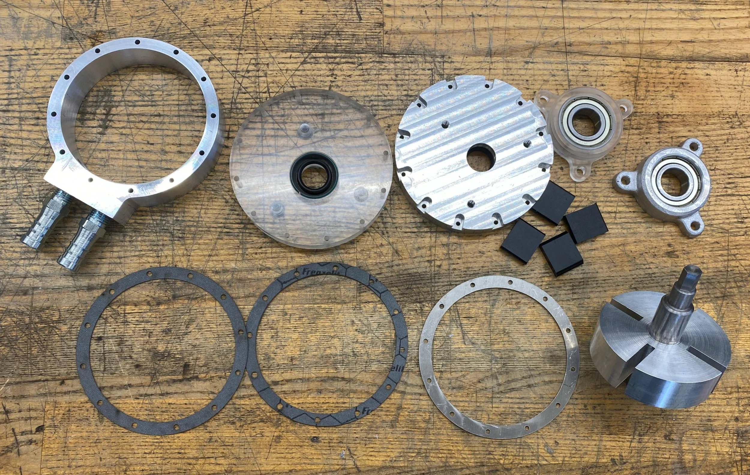
Flatlay of Pump Components

Assembled Pump
Testing Pump with a Drill