
Portable Shower Tank
This project was completed for the ‘Advanced Product Design and Engineering’ course at Boston University. Our team decided to design a portable shower that could function solely mechanically, and I was in charge of the tank containing the water. I designed the tank to be manufactured using structural foam moulding and supersonic welding, adhering to wall thickness constraints whilst still making it large enough to hold the pumping mechanism (an air bladder) and sufficient water for showering. In addition, I designed and, with a CNC lathe, turned custom-sized NPT heat inserts for hoses to attach to and connect the pump and shower handle components of the product.
A true-to-size model was made using 3D-printed carbon fibre nylon filament in an attempt to simulate the required wall strength for the system to function under pressure. Smaller prototypes were also made to test different aspects of the tank, such as the effectiveness of the bayonet mount for linking the top and bottom parts of the tank. Unfortunately, this model was not water-tight enough to function as needed.
This project was a great exercise in how to take a larger product and separate it into subsystems for design and construction. Our team of three each took control of one of the items, discussing often with each other to ensure these would work appropriately within the whole system. It also helped me have some hands-on experience with the limitations of rapid prototypes — whilst the 3D prints were helpful in determining how to best design mating features and the overall fit of the parts of the tank, it wasn’t the best representation of water-tightness nor dimensional accuracy due to layer thicknesses.
Collaborators
Ian Hedin
Matt Cowley
Skills
Material and Manufacturing Selection
CAD (OnShape)
GD&T and Process Drawings
CNC Turning
3D Printing Prototyping

Design Components
The main design considerations were around the manufacturing process, such as wall thickness, wall angles, and radii to allow for the structural foam moulding process. The images below show some of these design choices, as well as close-ups of those made for the bottom part of the tank. The turned NPT heat insert is also shown.
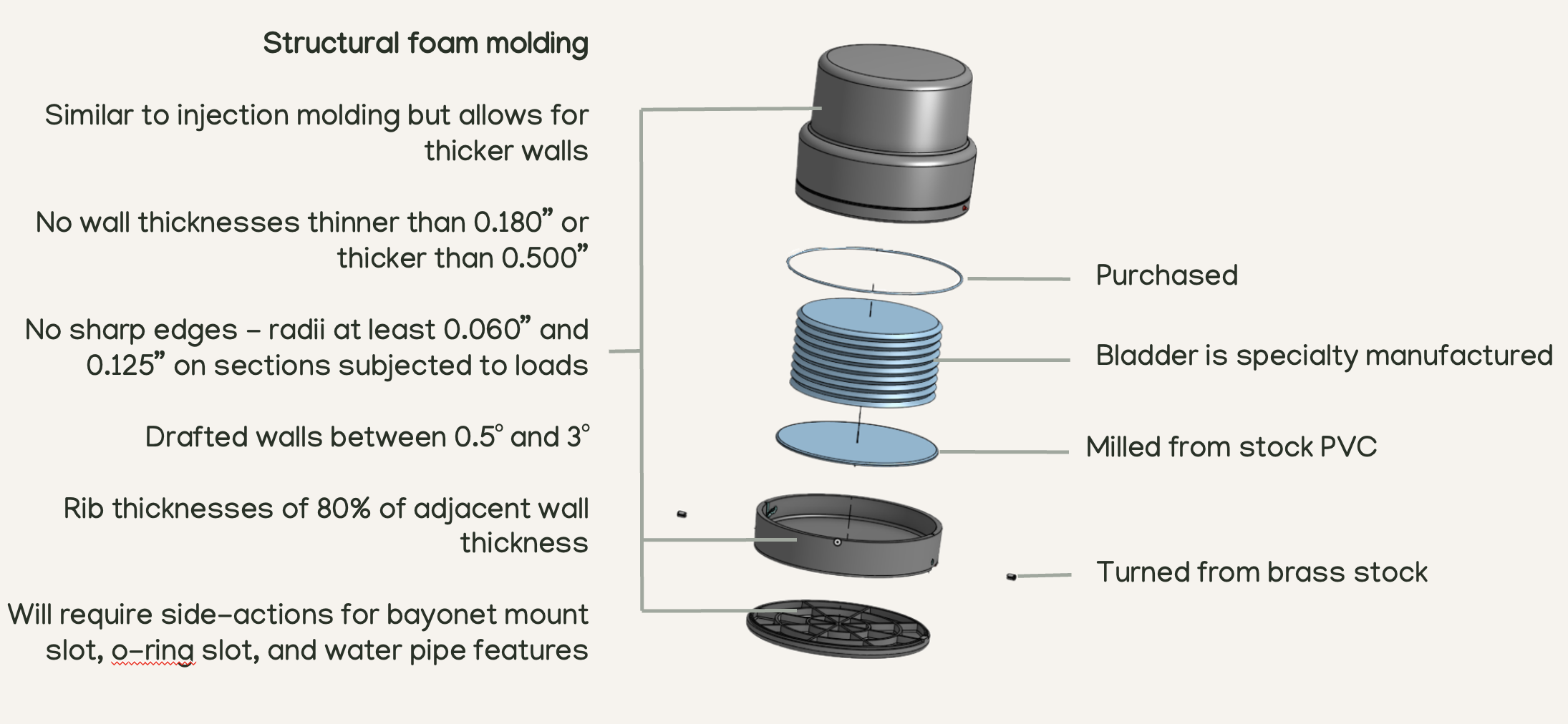
Overview of design choices made for all tank components
Part and Process Drawings
The drawing package for the tank is shown in the embedded PDF. It contains both the GD&T of the parts and the process drawings for the manufacturing of these, including details on parting lines and surface finishes.
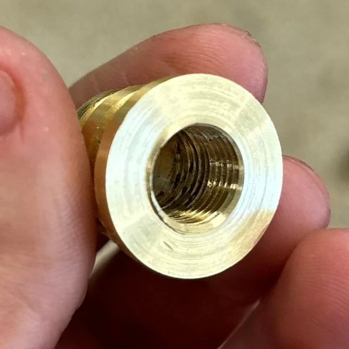
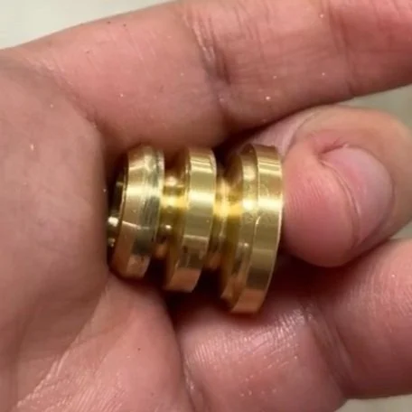
Custom NPT heat insert turned from brass stock on a CNC lathe
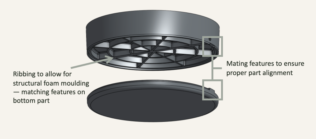
Ribbing and mating part design for bottom part of tank
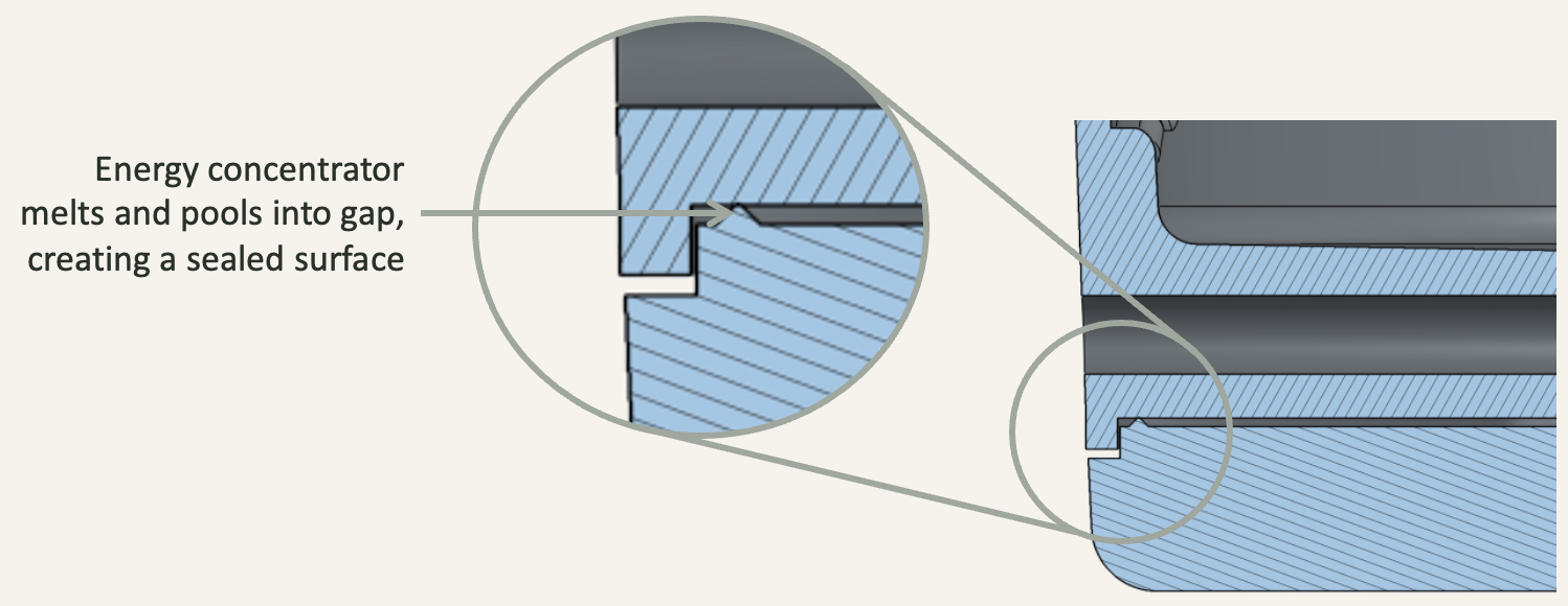
Energy concentrator design for ultrasonic welding on bottom part of tank