Smart Rat Trap

This project was completed during my sophomore year for the ‘Introduction to Engineering Design’ course. It consisted of designing and making a prototype of a rat trap that would notify the user once a rodent was trapped and allow for remote release of the animal.
This project was completed alongside Vincent Cheung, Nadim El Helou, Michelle Imogu, and Samuel Cook. I concentrated on designing and building the mechanical components of the trap alongside Cheung and Cook, while El Helou and Imogu managed the electronic components.
The written report for this project can be found here.
Objectives, Metrics, and Constraints
The project was given to our team with a set of constraints and objectives for us to adhere to. Below are tables demonstrating these constraints and objectives and how our group decided to address them.
| Objectives | Metrics |
|---|---|
| Attract rodent | Use bait to attract at least 1 rodent to the trap. |
| Catch rodent | Container must have dimensions 15 in x 6 in x 9 in to fit rodent. Must be able to catch rodents ranging from 0.05 lb to 1.5 lb. |
| Notify client when rodent is caught | Notify within 30 minutes of capture regardless of user location (no limiting distance). |
| Affordable | Use materials and manufacturing process that make trap cost < $150. |
| Don’t kill rodent | Keep rodent alive for 1 day. |
| Portability | Trap must not be larger than 15 in x 6 in x 9 in and must not weigh more than 15 lb (including mass of rodent). |
| Water-proof | Trap must be sealable to prevent water intake, and the material of the trap must be water-resistant. |
| Durable | Cleanable and reusable for 100 times. |
| Remote release | The release must be remotely activated within a minimum distance of 3 yards. |
| Constraints | Metrics |
|---|---|
| Safe for user (no contact with rodent) | Release should work even when user is more than 3 meters away. |
| Budget | Cost no more than $400 to manufacture prototype. |
| Aesthetics | Cannot be clear / transparent to minimise human-rodent interaction and to prevent predators. |
| Time | The product must be completed by the end of the semester. |
Rat Trap Design and Manufacturing
Based on the constraints and objectives of the project, our group brainstormed a variety of ways we could complete the requirements and decided to base our design on mainly mechanical components. The rodent would be trapped by releasing a spring-loaded door once it entered the box, pressing a button which would set off an SMS message to be sent to the user. For release, the user would be able to press a button to begin a timer before a solenoid was set off to allow the exit door to open. Below we can see a drawing of the design as well as a glass box diagram showing the general functioning of the product.


The parts were designed using Creo Parametric, and were then machined using the CNC Mills at Boston University’s Engineering Product Innovation Centre (EPIC). The video to the right shows some of the GibbsCAM processes used to create the outer shell.
Mathematical Model and Testing
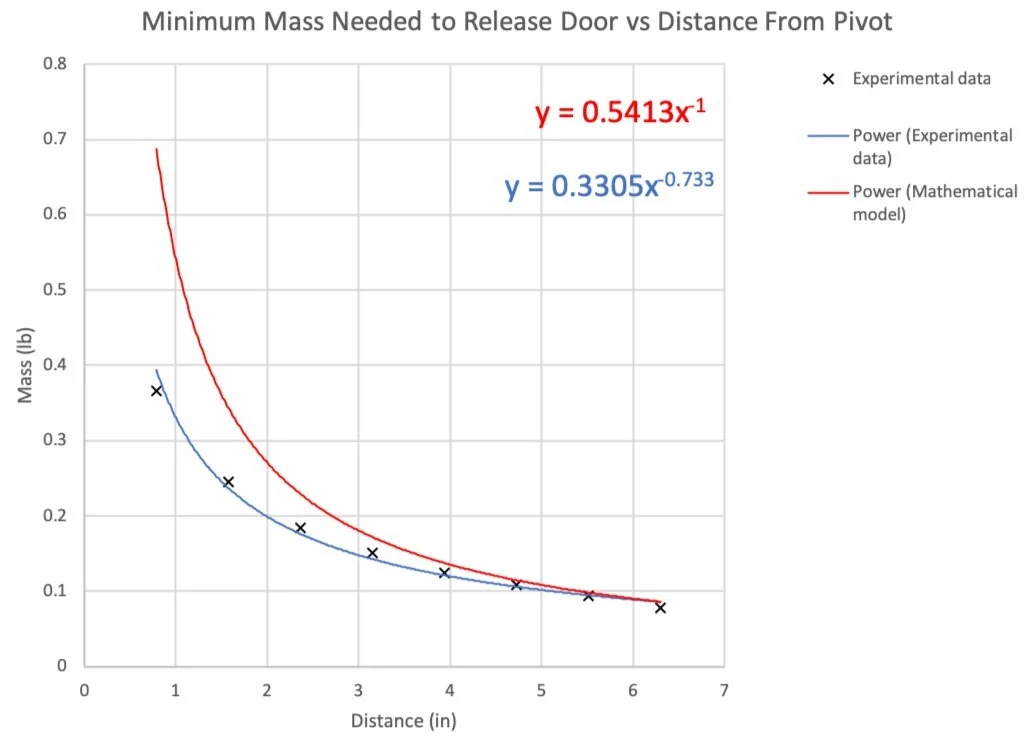
To ensure that the trapping mechanism worked as intended, we modelled the design using a free-body-diagram analysis of the moments and forces affecting the system based on our predetermined design and components.


We then plotted this theoretical model against experimental data, and found that, although the mechanism deviated from the theory, it was still functional as it was triggered at a maximum mass of around 0.37 lb when the average mass of the rodents we intended to catch was 0.34 lb. Since the intended usage was for the bait to be placed at the very back of the trap, we also ensured that even smaller rodents would be caught as at this point only about 0.09 lb were required to trigger the trapping mechanism.
Product Demonstration
Project Takeaways
This project was my first exposure to CAM software through GibbsCAM, so it left me with good technical knowledge regarding how to turn a CAD model into a physical part. In addition to this, the project overall allowed me to design a product from scratch in order to meet certain metrics, which was a great experience as we had to work as a team to find a solution that was feasible and useful, presenting our prototype alongside a written report to demonstrate our design process.
One of the more interesting aspects of the project to me was the teamwork. We worked in cells wherein the electrical and computer engineers managed the Arduino and created the electronic components of the trap, while the mechanical engineers managed the design and construction of the trapping system and case. We were quite efficient in doing this, and this experience showed me that it is much more efficient to divide up the work by specialty than expect everyone to be fully engaged in every aspect of the design.